Part 01: Building a scalable Jenkins server on a Kubernetes Cluster
System Architecture and Design


Introduction
Continuous Integration, which integrates all DevOps operations, is an essential part of DevOps. Jenkins is the most well-known Continuous Integration tool. Have you ever wondered why Jenkins has been so popular in recent years? One of the key factors contributing to its popularity is the Jenkins pipeline.
For embedded software teams, CI/CD is helpful. The procedure may appear daunting at first, especially because embedded systems sometimes need custom hardware. Yet, once the technique is in place, it may help in the early discovery of problems, saving time and money.
Thus, we devote this series to designing a scalable system using Jenkins and Kubernetes.
The series has two parts. The first part, currently reading, discusses the system's architecture. In the second part, we are going to discuss the implementation and results.
Problem Statement
At SEITech Solutions, we were using a single Jenkins server to handle our continuous integration and delivery tasks. So, the only way to scale the server is vertical scaling.
Once the team's size started to explode, problems start to appear. Examples of these flaws:
- Jenkins downtime increases.
- Long build queues.
- Dependency hell due to different tools for each project.
Proposed Solution
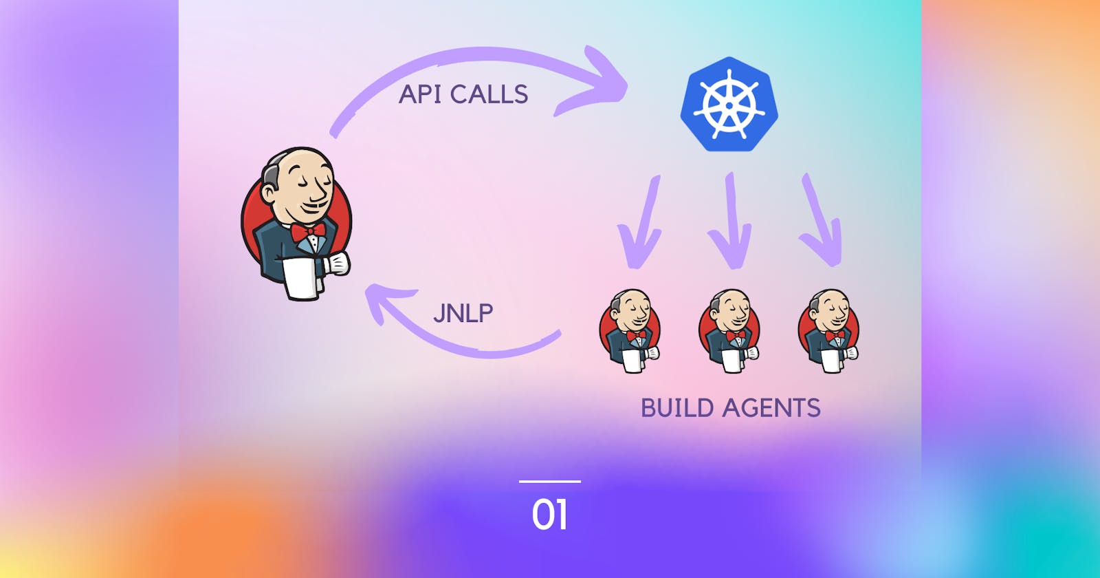
Operating a Jenkins controller on a K8s cluster is the main method to put in place. So, Jenkins agents will auto-scale as K8s pods with custom docker images.
Additionally, we take an advantage of using Jenkins Configuration as Code. This approach aligns with the X as Code descent approaches.
The following lists summarize the pros and cons of this approach.
Pros
- Increasing the velocity of developers writing, building, and testing their code.
- Customizing the agent pod to use different tools based on Docker images.
- Decreasing the downtime of Jenkins.
- Separating the Jenkins infrastructure administration from actual pipelines.
Cons
- The need for human resources to track and maintain the infrastructure.
- Increase in infrastructure cost on cloud providers.
System Architecture and Design
Let's start the adventure and check the system architecture of the system. Generally, you can apply this design on any cloud provider or on-premises. In this section, we will discuss AWS and Azure approaches. You have to note that actual product design will compromise more components. For example, adding more security layers and artifacts management like Jfrog.
Overall System Architecture
The following figure shows the key components that make up the system.
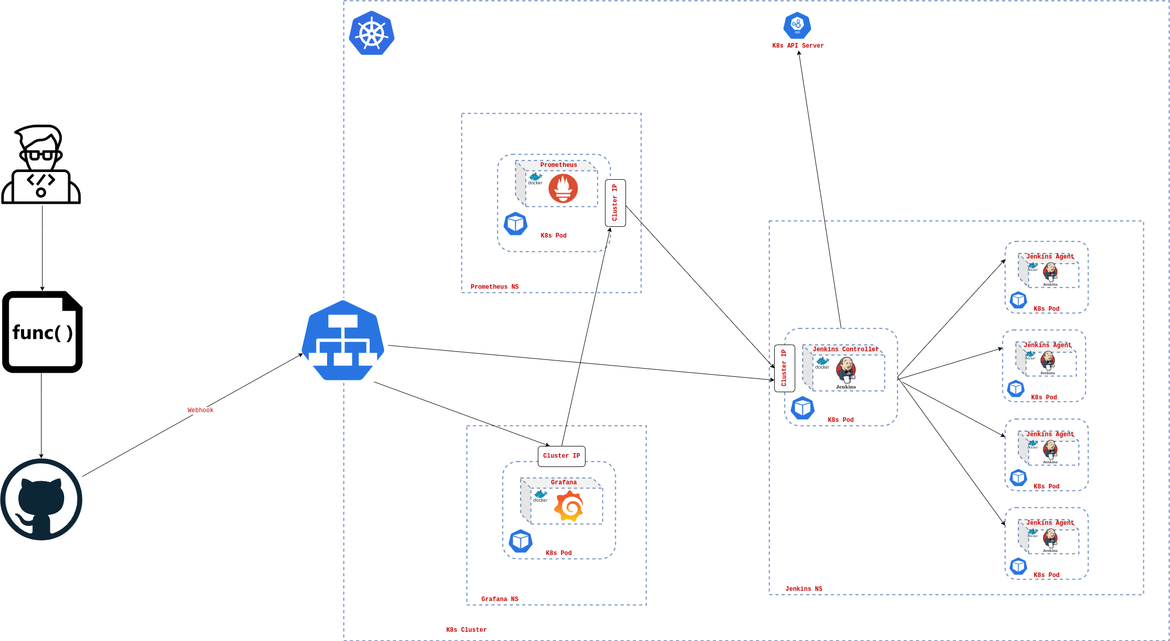
- Kubernetes Cluster
- Jenkins Server
- Prometheus
- Grafana
- GitHub
We mentioned before the importance of separation between the pipeline and the infrastructure. This approach is depicted in the last figure. For example, the developer will push his code with a custom Jenkins pipeline defined declaratively. Using GitHub webhooks, the Jenkins server calls the K8s API server to create a new pod. This new pod is will act as the agent to run the defined pipeline in the Jenkinsfile.
Moreover, the new pod contains the Jenkins agent and another helper tool (Jenkins Inbound agent) to facilitate communication between the Jenkins controller and the agent. After running the pipeline on each pod on the cluster that scales automatically reacting to the workload, it reports the findings like test reports and build artifacts to the reporting component and then de-provisioned automatically.
The last mentioned workflow illustrates the key system's role and benefits. It prevents developers from being blocked due to another build failed or even the automation server failure. Because each developer will run the pipeline in his own pod with his customizable environment without dependency on the others to finish building.
The solution also integrates reporting and alert managing tools like Prometheus and Grafana. Their role as in any other infrastructure, helping the admin to monitor the health of the system.
In the following subsections, we will dive into the design of this architecture on different cloud providers like AWS and Azure.
AWS Cloud Architecture
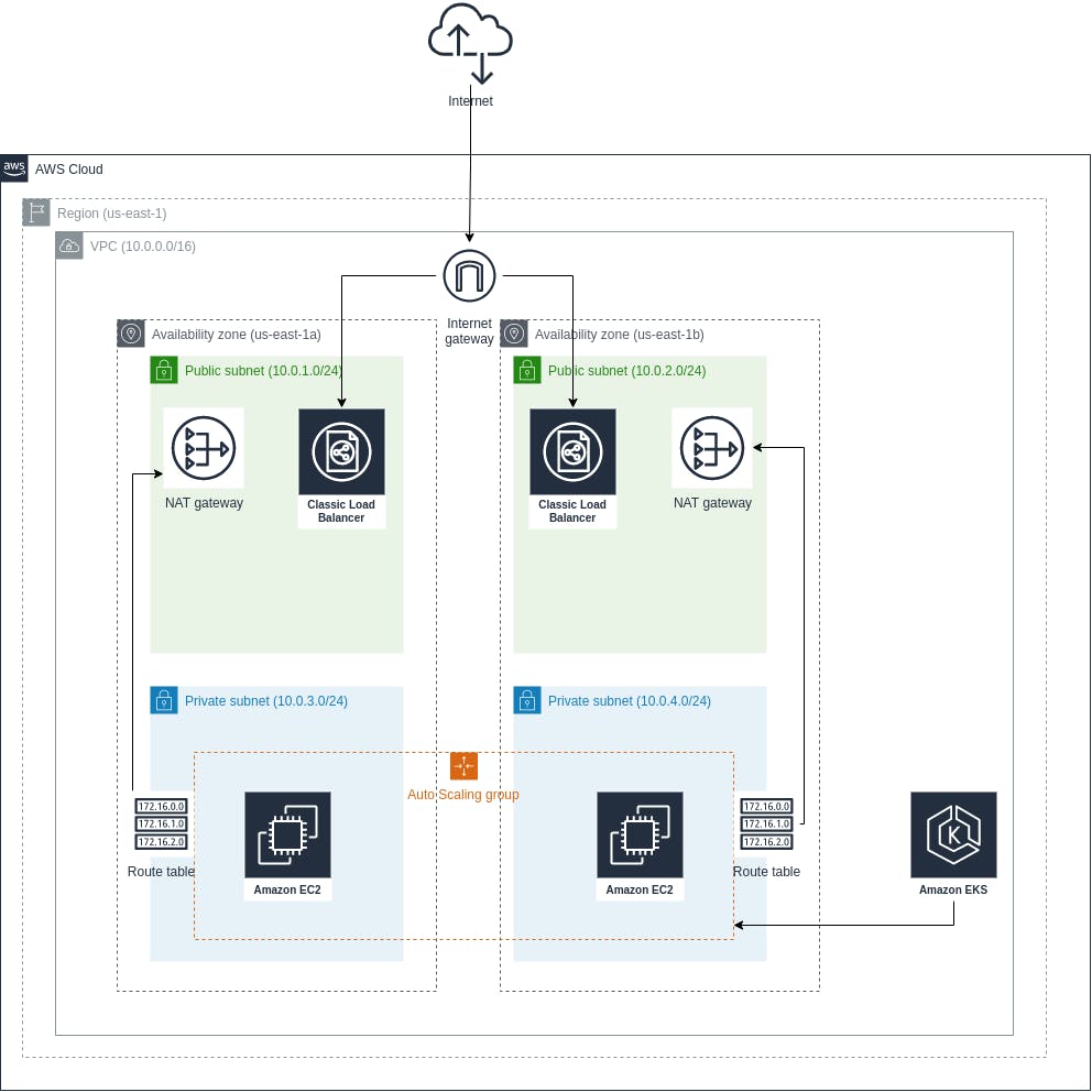
As shown in the figure, the system is divided into different parts, some related to AWS cloud concepts and others related to the automation server. Let's divide these components and define each of them.
- The AWS region: this component is intrinsic in the AWS cloud. Simply put, a region is an aggregation of distributed and independent but connected data centers.
- The AWS VPC: this considers the basic networking infrastructure for the region. It defines an address space to use within this VPC. We define the address space using CIDR notation which is (10.0.0.0/16).
- The AWS Availability Zone: is one or more discrete data centers with redundant power, networking, and connectivity in an AWS Region. We use here two availability zones (us-east-1a and us-east-1b).
- The Public and Private Subnets: in general, subnets are a logical portion of the address space defined in the VPC. As understood from the naming, the private subnet is not facing the internet while the public subnet faces the public internet. The figure also shows the address space in the subnets defined in the same notation used before.
- The LoadBalancers: are used in the public subnet to automatically distribute the incoming application traffic across multiple targets and virtual appliances in one or more Availability Zones (AZs).
- The Internet Gateway: is used in allowing communication between the VPC and the public internet.
- The NAT Gateway: is used in allowing communication between the deployed services in the private subnets and the public internet but not in the opposite direction.
- The Route Table: contains a set of rules, called routes, that determine where network traffic from the private subnet or gateway is directed.
- The AWS EKS: is the Kubernetes managed service by AWS.
- The Autoscaling Group: defines a group of nodes that auto-scales automatically reacting to the incoming load.
- The AWS EC2: is a managed virtual machine by AWS. It is used by EKS as the backbone of the deploying facility to run the Docker containers on.
In the next part, we will deep dive into the implementation of this architecture using Terraform Infrastructure as a Code tool.
Azure Cloud Architecture
There is no huge difference in the Azure architecture relative to the AWS architecture. The following table summarizes the key differences between both cloud providers.
| AWS | Azure |
| VPC | Vnet |
| IAM User | Service Principal |
Additionally, there are a few differences in some implementation details of provisioning the K8s cluster.
Conclusion
This part discussed the problem statement and its business implications. Not to mention the system design and workflow discussions. Right now, we have the ground for the next part of this article which will be concentrating on discussing the implementation details of this architecture.
References
1- Jenkins on Kubernetes Engine: cloud.google.com/architecture/jenkins-on-ku..
2- Jenkins high availability and disaster recovery on AWS: aws.amazon.com/blogs/devops/jenkins-high-av..